WHEATSTONE BRIDGE
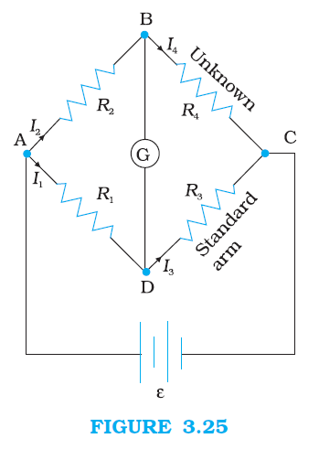
`color{blue} ✍️` As an application of Kirchhoff’s rules consider the circuit shown in Fig. 3.25, which is called the Wheatstone bridge.
`color{blue} ✍️` The bridge has four resistors `color{blue}(R_1, R_2, R_3)` and `R_4`. Across one pair of diagonally opposite points (A and C in the figure) a source is connected. This (i.e., AC) is called the battery arm.
`color{blue} ✍️` Between the other two vertices, B and D, a galvanometer G (which is a device to detect currents) is connected. This line, shown as `BD` in the figure, is called the galvanometer arm.
`color{blue} ✍️` For simplicity, we assume that the cell has no internal resistance. In general there will be currents flowing across all the resistors as well as a current `I_g` through `G`. Of special interest, is the case of a balanced bridge where the resistors are such that `I_g = 0`.
`color{blue} ✍️` We can easily get the balance condition, such that there is no current through `G`. In this case, the Kirchhoff’s junction rule applied to junctions `D` and ` B` (see the figure) immediately gives us the relations `color{blue}(I_1 = I_3)` and `color{blue}(I_2 = I_4)`.
`color{blue} ✍️` Next, we apply Kirchhoff’s loop rule to closed loops ADBA and CBDC. The first loop gives
`=>` and the second loop gives, upon using `color{blue}(I_3 = I_1, I_4 = I_2)`
From Eq. (3.81), we obtain, `color{blue}((I_1)/(I_2) = (R_2)/(R_1))`
whereas from Eq. (3.82), we obtain, `color{blue}((I_1)/(I_2) = (R_4)/(R_3))`
Hence, we obtain the condition
`color{blue} ✍️` This last equation relating the four resistors is called the balance condition for the galvanometer to give zero or null deflection.
`color{blue} ✍️` The Wheatstone bridge and its balance condition provide a practical method for determination of an unknown resistance.
`color{blue} ✍️` Let us suppose we have an unknown resistance, which we insert in the fourth arm; `R_4` is thus not known. Keeping known resistances `R_1` and `R_2` in the first and second arm of the bridge, we go on varying `R_3` till the galvanometer shows a null deflection.
`color{blue} ✍️` The bridge then is balanced, and from the balance condition the value of the unknown resistance `R_4` is given by
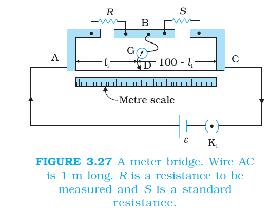
`color{blue} ✍️` A practical device using this principle is called the meter bridge. It will be discussed in the next section.
`color{blue} ✍️` The bridge has four resistors `color{blue}(R_1, R_2, R_3)` and `R_4`. Across one pair of diagonally opposite points (A and C in the figure) a source is connected. This (i.e., AC) is called the battery arm.
`color{blue} ✍️` Between the other two vertices, B and D, a galvanometer G (which is a device to detect currents) is connected. This line, shown as `BD` in the figure, is called the galvanometer arm.
`color{blue} ✍️` For simplicity, we assume that the cell has no internal resistance. In general there will be currents flowing across all the resistors as well as a current `I_g` through `G`. Of special interest, is the case of a balanced bridge where the resistors are such that `I_g = 0`.
`color{blue} ✍️` We can easily get the balance condition, such that there is no current through `G`. In this case, the Kirchhoff’s junction rule applied to junctions `D` and ` B` (see the figure) immediately gives us the relations `color{blue}(I_1 = I_3)` and `color{blue}(I_2 = I_4)`.
`color{blue} ✍️` Next, we apply Kirchhoff’s loop rule to closed loops ADBA and CBDC. The first loop gives
`color{blue}(–I_1 R_1 + 0 + I_2 R_2 = 0 \ \ \ \ (Ig = 0))`
.........(3.81)`=>` and the second loop gives, upon using `color{blue}(I_3 = I_1, I_4 = I_2)`
`color{blue}(I_2 R_4 + 0 – I_1 R_3 = 0)`
...........(3.82)From Eq. (3.81), we obtain, `color{blue}((I_1)/(I_2) = (R_2)/(R_1))`
whereas from Eq. (3.82), we obtain, `color{blue}((I_1)/(I_2) = (R_4)/(R_3))`
Hence, we obtain the condition
`color{blue}((R_2)/(R_1) = (R_4)/(R_3))`
...........[3.83(a)]`color{blue} ✍️` This last equation relating the four resistors is called the balance condition for the galvanometer to give zero or null deflection.
`color{blue} ✍️` The Wheatstone bridge and its balance condition provide a practical method for determination of an unknown resistance.
`color{blue} ✍️` Let us suppose we have an unknown resistance, which we insert in the fourth arm; `R_4` is thus not known. Keeping known resistances `R_1` and `R_2` in the first and second arm of the bridge, we go on varying `R_3` till the galvanometer shows a null deflection.
`color{blue} ✍️` The bridge then is balanced, and from the balance condition the value of the unknown resistance `R_4` is given by
`color{blue}(R_4 = R_3 (R_2)/(R_1))`
.........[3.83(b)]`color{blue} ✍️` A practical device using this principle is called the meter bridge. It will be discussed in the next section.