LENZ’S LAW AND CONSERVATION OF ENERGY
`color{blue} ✍️` In 1834, German physicist Heinrich Friedrich Lenz (1804-1865) deduced a rule, known as Lenz’s law which gives the polarity of the induced emf in a clear and concise fashion. The statement of the law is:
`color{purple}{"he polarity of induced emf is such that it tends to produce a "}`
`color{purple}{"current which opposes the change in magnetic flux that produced it. "}`
`color{blue} ✍️`The negative sign shown in Eq. (6.3) represents this effect. We can understand Lenz’s law by examining Experiment 6.1 in Section 6.2.1. In Fig. 6.1, we see that the North-pole of a bar magnet is being pushed towards the closed coil.
`color{blue} ✍️`As the North-pole of the bar magnet moves towards the coil, the magnetic flux through the coil increases.
`color{blue} ✍️`Hence current is induced in the coil in such a direction that it opposes the increase in flux. This is possible only if the current in the coil is in a counter-clockwise direction with respect to an observer situated on the side of the magnet.
`color{brown}bbul{"Note"}` that magnetic moment associated with this current has North polarity towards the North-pole of the approaching magnet.
`color{blue} ✍️`Similarly, if the Northpole of the magnet is being withdrawn from the coil, the magnetic flux through the coil will decrease. To counter this decrease in magnetic flux, the induced current in the coil flows in clockwise direction and its South-pole faces the receding North-pole of the bar magnet.
`color{blue} ✍️`This would result in an attractive force which opposes the motion of the magnet and the corresponding decrease in flux.
`color{blue} ✍️`Suppose if an open circuit is used in place of the closed loop in the above example, In this case too, an emf is induced across the open ends of the circuit. The direction of the induced emf can be found using Lenz’s law.
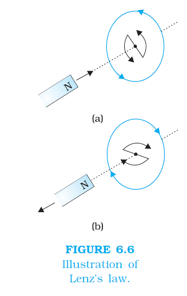
`color{blue} ✍️`Consider Figs. 6.6 (a) and (b). They provide an easier way to understand the direction of induced currents. Note that the direction shown by indicate the directions of the induced currents.
`color{blue} ✍️`A little reflection on this matter should convince us on the correctness of Lenz’s law. Suppose that the induced current was in the direction opposite to the one depicted in Fig. 6.6(a).
`color{blue} ✍️` In that case, the South-pole due to the induced current will face the approaching North-pole of the magnet.
The bar magnet will then be attracted towards the coil at an ever increasing acceleration. A gentle push on the magnet will initiate the process and its velocity and kinetic energy will continuously increase without expending any energy.
`color{blue} ✍️`If this can happen, one could construct a perpetual-motion machine by a suitable arrangement. This violates the law of conservation of energy and hence can not happen.
`color{blue} ✍️`Now consider the correct case shown in Fig. 6.6(a). In this situation, the bar magnet experiences a repulsive force due to the induced current. Therefore, a person has to do work in moving the magnet.
`color{blue} ✍️`Where does the energy spent by the person go? This energy is dissipated by Joule heating produced by the induced current.
`color{purple}{"he polarity of induced emf is such that it tends to produce a "}`
`color{purple}{"current which opposes the change in magnetic flux that produced it. "}`
`color{blue} ✍️`The negative sign shown in Eq. (6.3) represents this effect. We can understand Lenz’s law by examining Experiment 6.1 in Section 6.2.1. In Fig. 6.1, we see that the North-pole of a bar magnet is being pushed towards the closed coil.
`color{blue} ✍️`As the North-pole of the bar magnet moves towards the coil, the magnetic flux through the coil increases.
`color{blue} ✍️`Hence current is induced in the coil in such a direction that it opposes the increase in flux. This is possible only if the current in the coil is in a counter-clockwise direction with respect to an observer situated on the side of the magnet.
`color{brown}bbul{"Note"}` that magnetic moment associated with this current has North polarity towards the North-pole of the approaching magnet.
`color{blue} ✍️`Similarly, if the Northpole of the magnet is being withdrawn from the coil, the magnetic flux through the coil will decrease. To counter this decrease in magnetic flux, the induced current in the coil flows in clockwise direction and its South-pole faces the receding North-pole of the bar magnet.
`color{blue} ✍️`This would result in an attractive force which opposes the motion of the magnet and the corresponding decrease in flux.
`color{blue} ✍️`Suppose if an open circuit is used in place of the closed loop in the above example, In this case too, an emf is induced across the open ends of the circuit. The direction of the induced emf can be found using Lenz’s law.
`color{blue} ✍️`Consider Figs. 6.6 (a) and (b). They provide an easier way to understand the direction of induced currents. Note that the direction shown by
indicate the directions of the induced currents. `color{blue} ✍️`A little reflection on this matter should convince us on the correctness of Lenz’s law. Suppose that the induced current was in the direction opposite to the one depicted in Fig. 6.6(a).
`color{blue} ✍️` In that case, the South-pole due to the induced current will face the approaching North-pole of the magnet.
The bar magnet will then be attracted towards the coil at an ever increasing acceleration. A gentle push on the magnet will initiate the process and its velocity and kinetic energy will continuously increase without expending any energy.
`color{blue} ✍️`If this can happen, one could construct a perpetual-motion machine by a suitable arrangement. This violates the law of conservation of energy and hence can not happen.
`color{blue} ✍️`Now consider the correct case shown in Fig. 6.6(a). In this situation, the bar magnet experiences a repulsive force due to the induced current. Therefore, a person has to do work in moving the magnet.
`color{blue} ✍️`Where does the energy spent by the person go? This energy is dissipated by Joule heating produced by the induced current.


