AC VOLTAGE APPLIED TO A RESISTOR
`color{blue} ✍️` Figure 7.1 shows a resistor connected to a source e of ac voltage. The symbol for an ac source in a circuit diagram is  . We consider a source which produces sinusoidally varying potential difference across its terminals. Let this potential difference, also called ac voltage, be given by
`color {blue}{➢➢}`where `v_m` is the amplitude of the oscillating potential difference and `omega` is its angular frequency.

`color {blue}{➢➢}`To find the value of current through the resistor, we apply Kirchhoff’s loop rule `sum epsilon(t ) = 0` , to the circuit shown in Fig. 7.1 to get
`sin = v_m omega t R`
or `t = (v_m)/R sin omegat`
`color {blue}{➢➢}`Since `R` is a constant, we can write this equation as
`color {blue}{➢➢}`where the current amplitude `i_m` is given by
`color {blue}{➢➢}`Equation (7.3) is just Ohm’s law which for resistors works equally well for both ac and dc voltages.
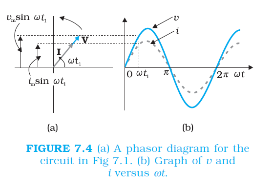
`color {blue}{➢➢}`The voltage across a pure resistor and the current through it, given by Eqs. (7.1) and (7.2) are plotted as a function of time in Fig. 7.2.

`color {brown} bbul{"Note"}`, in particular that both v and i reach zero, minimum and maximum values at the same time.
`color {blue}{➢➢}`Clearly, the voltage and current are in phase with each other. We see that, like the applied voltage, the current varies sinusoidally and has corresponding positive and negative values during each cycle.
`color {blue}{➢➢}`Thus, the sum of the instantaneous current values over one complete cycle is zero, and the average current is zero. The fact that the average current is zero, however, does not mean that the average power consumed is zero and that there is no dissipation of electrical energy.
`color {blue}{➢➢}`As you know, Joule heating is given by `i^2 R` and depends on `i^2` (which is always positive whether `i` is positive or negative) and not on `i.`
`color {blue}{➢➢}`Thus, there is Joule heating and dissipation of electrical energy when an ac current passes through a resistor. The instantaneous power dissipated in the resistor is
`color {blue}{➢➢}`The average value of `p` over a cycle is*
`color {blue}{➢➢}`where the bar over a letter(here, `p`) denotes its average value and <......> denotes taking average of the quantity inside the bracket. Since, i_(m)^(2) and `R` are constants,
`color {blue}{➢➢}`Using the trigonometric identity, `sin2 wt = 1/2 (1– cos 2omegat ),` we have `< sin^2 omegat > = (1/2) (1– < cos 2omegat >)`
and since `< cos2omegat > = 0**`, we have,
`< sin^2 omegat> = 1/2`
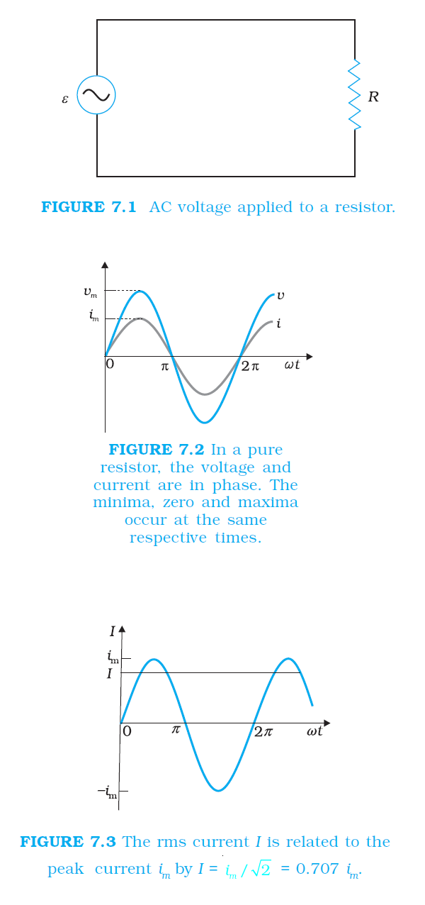
`color {blue}{➢➢}`To express ac power in the same form as dc power `(P = I^2R),` a special value of current is defined and used.
It is called, root mean square (rms) or effective current (Fig. 7.3) and is denoted by `I_(rms)` or `I`.

`color {blue}{➢➢}`It is defined by
`color {blue}{➢➢}`In terms of I, the average power, denoted by P is
`color {blue}{➢➢}`Similarly, we define the rms voltage or effective voltage by
From Eq. (7.3), we have
`v_m = i_mR`
or , `(v_m)/(sqrt2) = (i_m)/(sqrt2) R`
or,
`color {blue}{➢➢}`Equation (7.9) gives the relation between ac current and ac voltage and is similar to that in the dc case.
`color {blue}{➢➢}`This shows the advantage of introducing the concept of `rms` values. In terms of `rms` values, the equation for power [Eq. (7.7)] and relation between current and voltage in ac circuits are essentially the same as those for the dc case. It is customary to measure and specify `rms` values for ac quantities. For example, the household line voltage of `220 V` is an `rms` value with a peak voltage of
`color {blue}{➢➢}`In fact, the `I` or rms current is the equivalent dc current that would produce the same average power loss as the alternating current. Equation
(7.7) can also be written as
. We consider a source which produces sinusoidally varying potential difference across its terminals. Let this potential difference, also called ac voltage, be given by`color {blue}{v = v_m sin omega t}`
...........(7.1)`color {blue}{➢➢}`where `v_m` is the amplitude of the oscillating potential difference and `omega` is its angular frequency.
`color {blue}{➢➢}`To find the value of current through the resistor, we apply Kirchhoff’s loop rule `sum epsilon(t ) = 0` , to the circuit shown in Fig. 7.1 to get
`sin = v_m omega t R`
or `t = (v_m)/R sin omegat`
`color {blue}{➢➢}`Since `R` is a constant, we can write this equation as
`color {blue}{t = t_m sin omega t}`
.............(7.2)`color {blue}{➢➢}`where the current amplitude `i_m` is given by
`color {blue}{i_m = (v_m)/R}`
............(7.3)`color {blue}{➢➢}`Equation (7.3) is just Ohm’s law which for resistors works equally well for both ac and dc voltages.
`color {blue}{➢➢}`The voltage across a pure resistor and the current through it, given by Eqs. (7.1) and (7.2) are plotted as a function of time in Fig. 7.2.
`color {brown} bbul{"Note"}`, in particular that both v and i reach zero, minimum and maximum values at the same time.
`color {blue}{➢➢}`Clearly, the voltage and current are in phase with each other. We see that, like the applied voltage, the current varies sinusoidally and has corresponding positive and negative values during each cycle.
`color {blue}{➢➢}`Thus, the sum of the instantaneous current values over one complete cycle is zero, and the average current is zero. The fact that the average current is zero, however, does not mean that the average power consumed is zero and that there is no dissipation of electrical energy.
`color {blue}{➢➢}`As you know, Joule heating is given by `i^2 R` and depends on `i^2` (which is always positive whether `i` is positive or negative) and not on `i.`
`color {blue}{➢➢}`Thus, there is Joule heating and dissipation of electrical energy when an ac current passes through a resistor. The instantaneous power dissipated in the resistor is
`color {blue}{p =i 2R =i_(m)^(R) sin^2omega t}`
........(7.4)`color {blue}{➢➢}`The average value of `p` over a cycle is*
`color {blue}{R = , i^2 R > = < i_(m)^(2) sin^2 omega t > }`
.........[7.5(a)]`color {blue}{➢➢}`where the bar over a letter(here, `p`) denotes its average value and <......> denotes taking average of the quantity inside the bracket. Since, i_(m)^(2) and `R` are constants,
`color {blue}{bar P = i_(m)^(2) R< sin^2 omega t > }`
.........[7.5(b)]`color {blue}{➢➢}`Using the trigonometric identity, `sin2 wt = 1/2 (1– cos 2omegat ),` we have `< sin^2 omegat > = (1/2) (1– < cos 2omegat >)`
and since `< cos2omegat > = 0**`, we have,
`< sin^2 omegat> = 1/2`
`color {blue}{➢➢}`Thus `color {blue}{bar P= 1/2i_(m)^(2)R}`
...........[7.5(c)]`color {blue}{➢➢}`To express ac power in the same form as dc power `(P = I^2R),` a special value of current is defined and used.
It is called, root mean square (rms) or effective current (Fig. 7.3) and is denoted by `I_(rms)` or `I`.
`color {blue}{➢➢}`It is defined by
`I = sqrt(i^2)= sqrt((1/2)i_(m)^(2)) = (i_m)/sqrt2`
`color {blue}{= 0.707 i_m}`
.............(7.6)`color {blue}{➢➢}`In terms of I, the average power, denoted by P is
`color {blue}{P = bar P= 1/2 i_(m)^(2) R = I^2R}`
.............(7.7)`color {blue}{➢➢}`Similarly, we define the rms voltage or effective voltage by
`color {blue}{V= (v_m)/(sqrt2)n = 0.707 v_m}`
.............(7.8)From Eq. (7.3), we have
`v_m = i_mR`
or , `(v_m)/(sqrt2) = (i_m)/(sqrt2) R`
or,
`color {blue}{V= IR}`
.............(7.9)`color {blue}{➢➢}`Equation (7.9) gives the relation between ac current and ac voltage and is similar to that in the dc case.
`color {blue}{➢➢}`This shows the advantage of introducing the concept of `rms` values. In terms of `rms` values, the equation for power [Eq. (7.7)] and relation between current and voltage in ac circuits are essentially the same as those for the dc case. It is customary to measure and specify `rms` values for ac quantities. For example, the household line voltage of `220 V` is an `rms` value with a peak voltage of
`color {blue}{V_M = sqrt2 V = (1.414)(220V) = 311V}`
`color {blue}{➢➢}`In fact, the `I` or rms current is the equivalent dc current that would produce the same average power loss as the alternating current. Equation
`color {blue}{P = V^2 / R = I V " " ("since "V = I R)}`
(7.7) can also be written as