LCR Series Circuit
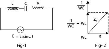
In this type of circuit a resistance `R`, inductor `L`, and a capacitor `C` are connected in series and the combination is connected across the terminals of an AC source `E = E_0sin(omega t)`.
The impedance and phase angle for the circuit is determined from the phase diagram below.
`Z = sqrt(R^2 + (X_C - X_L)^2) = sqrt(R^2 + (1/(omega C) -omega L)^2)`
`phi = tan^-1((X_C-X_L)/R)`
The instantaneous current can therefore be expressed as
`i = i_0 sin(omega t +phi)` where `i_0 =E_0/Z` is the peak voltage.
Now, the quantity `(X_C-X_L)` is called the 'reactance' of the given circuit. If the reactance is a positive quantity (i.e. `(X_C < X_L )` , the current 'leads' ahead of the voltage whereas if the reactance is a negative quantity (i.e. `(X_C < X_L)` , the current 'lags' behind of the voltage.