TRANSFORMER
A transformer is an electrical device that works on the principle of mutual induction to convert a given AC voltage into a larger voltage (step-up transformer) or a lower voltage (step-down transformer).
`text(Principle :)`
If two coils are inductively coupled (mutual inductance) and the current or magnetic flux linked with one is continuously changing with time, then an induced EMF is produced in the second coil. Therefore, if the current fed into the primary is an Alternating Current, then the time varying magnetic flux and the resulting induced voltage in the secondary will also be alternating and with the identical angular frequency.
`text(Schematic Design :)`
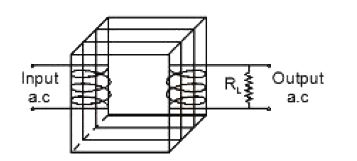
A schematic diagram for a transformer is shown here.
The transformer consists of a rectangular soft iron core made up of laminated sheets, well insulated from one another with two sets of coils on either side, the primary and the secondary. The soft-iron core causes the two sets of coils to be magnetically linked (i.e. there is 'coupling'and hence mutual inductance) such that when an alternating current is passed through the primary coil it induces a magnetic flux in the secondary.
Let the input voltage supplied by `AC` source is
`E = E_0Sin(omega t)`
Now, this creates an induced emf `E_p` across the primary coil due to EMI. Similarly, an induced emf `E_s` , appears across the secondary. If `N_p` is the number of turns in the primary and `N_s` , in the secondary coils, then,
`E_s/E_p = N_s/N_p`
The term `N_s/N_p =k` is called the transformation ratio and depending on it's value (i.e. `> 1 or < 1)` the transformer has a step-up or a step-down function. In a step-up transformer, the primary coil is made of a few turns of copper wire whereas the secondary coil consists of large number of turns of copper wire. In a step-down transformer, the primary coil consists of large number of turns of insulated copper wire whereas the secondary coil consists of few turns of fine insulated copper wire.
`text(Principle :)`
If two coils are inductively coupled (mutual inductance) and the current or magnetic flux linked with one is continuously changing with time, then an induced EMF is produced in the second coil. Therefore, if the current fed into the primary is an Alternating Current, then the time varying magnetic flux and the resulting induced voltage in the secondary will also be alternating and with the identical angular frequency.
`text(Schematic Design :)`
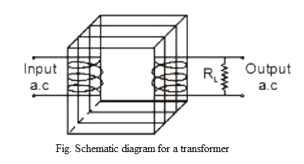
A schematic diagram for a transformer is shown here.
The transformer consists of a rectangular soft iron core made up of laminated sheets, well insulated from one another with two sets of coils on either side, the primary and the secondary. The soft-iron core causes the two sets of coils to be magnetically linked (i.e. there is 'coupling'and hence mutual inductance) such that when an alternating current is passed through the primary coil it induces a magnetic flux in the secondary.
Let the input voltage supplied by `AC` source is
`E = E_0Sin(omega t)`
Now, this creates an induced emf `E_p` across the primary coil due to EMI. Similarly, an induced emf `E_s` , appears across the secondary. If `N_p` is the number of turns in the primary and `N_s` , in the secondary coils, then,
`E_s/E_p = N_s/N_p`
The term `N_s/N_p =k` is called the transformation ratio and depending on it's value (i.e. `> 1 or < 1)` the transformer has a step-up or a step-down function. In a step-up transformer, the primary coil is made of a few turns of copper wire whereas the secondary coil consists of large number of turns of copper wire. In a step-down transformer, the primary coil consists of large number of turns of insulated copper wire whereas the secondary coil consists of few turns of fine insulated copper wire.