`text(Pole (vertex) ): ` Point of intersection of principal axis and the refracting surface.
`text(Focal Point (F) ) : ` It is an axial point having the property that any incident ray traveling parallel to the axis will after refraction, proceed toward, or appear to come from this point.
`text(Focal length (f) ) : ` The distance of the focus from the vertex of the refracting surface is called focal length. There is a great significance of the sign of focal length as it is able to state whether the spherical refracting surface is converging or diverging as in the chart.
`text(Sign of f : )`
+ ve `->` Converging nature of system.
- ve `->` Diverging nature of system.
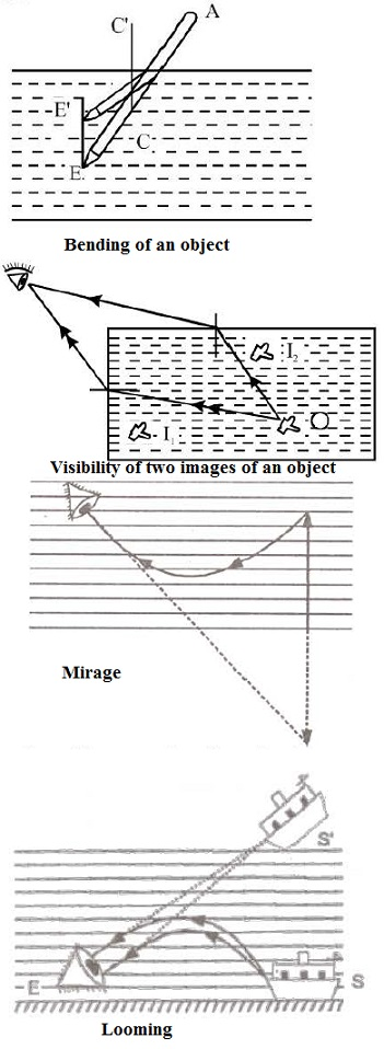
In this section we describe how images are formed when light rays are refracted at the boundary between two transparent materials.
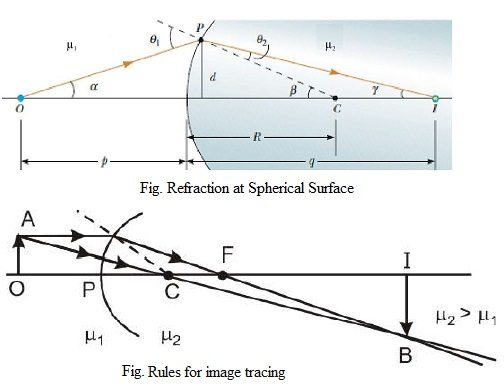
Consider two transparent media having indices of refraction `mu_1` and `mu_2`, where the boundary between the two media is a spherical surface of radius R (Fig.). We assume that the object at O is in the medium for which the index of refraction is `mu_1`. Let us consider the paraxial rays leaving O. As we shall see, all such rays are refracted at the spherical surface and focus at a single point `I`, the image point. Figure shows a single ray leaving point O and refracting to point I.
Snell's law of refraction applied to this ray gives
`mu_1sintheta_1=mu_2sintheta_2`
Because `theta_1` and `theta_2` are assumed to be small, we can use the small-angle approximation `sinthetaapproxtheta` (with angles in radians) and say that
`mu_1theta_1=mu_2theta_2`
Now we use the fact that an exterior angle of any triangle equals the sum of the two opposite interior angles. Applying this rule to triangles OPC and PIC in Figure gives
`theta_1=alpha+beta`
`beta=theta_2+gamma`
If we combine all three expressions and eliminate `theta_1`, and `theta_2`, we find that
`mu_1alpha+mu_2gamma=(mu_2-mu_1)beta`
From Figure, we see three right triangles that have a common vertical leg of length d. For paraxial rays (unlike the relatively large-angle ray shown in Fig.), the horizontal legs of these triangles are approximately p for the triangle containing angle `alpha`, R for the triangle containing angle `beta`, and q for the triangle containing angle `gamma` ). In the small-angle approximation, `tanalphaapproxalpha`, so we can write the approximate relationships from these triangles as follows:
`tanalphaapproxalpha=d/p`
`tanbetaapproxbeta=d/R`
`tangammaapproxgamma=d/q`
We substitute these expressions into above Equation and divide through by d to give
`(mu_2)/p + (mu_1)/q = (mu_2-mu_1)/R`
Let
u = object distance (with sign convention)
v = image distance (with sign convention)
R = Radius of curvature (with sign convention)
then
`p=-u`
`q=+v`
`R=+R`
putting the values of p, q and R in above equation we get
`(mu_2)/v -(mu_1)/u = (mu_2-mu_1)/R`
`text(Rules for image tracing for a linear, transverse extended object : )`
The basic rule is same as that in mirrors. Briefly,
(i) Draw a ray parallel to the principal axis which after refraction will be along the line passing through F.
(ii) Draw a ray incident along the line through centre it will pass undeviated.
`text(Pole (vertex) ): ` Point of intersection of principal axis and the refracting surface.
`text(Focal Point (F) ) : ` It is an axial point having the property that any incident ray traveling parallel to the axis will after refraction, proceed toward, or appear to come from this point.
`text(Focal length (f) ) : ` The distance of the focus from the vertex of the refracting surface is called focal length. There is a great significance of the sign of focal length as it is able to state whether the spherical refracting surface is converging or diverging as in the chart.
`text(Sign of f : )`
+ ve `->` Converging nature of system.
- ve `->` Diverging nature of system.
In this section we describe how images are formed when light rays are refracted at the boundary between two transparent materials.
Consider two transparent media having indices of refraction `mu_1` and `mu_2`, where the boundary between the two media is a spherical surface of radius R (Fig.). We assume that the object at O is in the medium for which the index of refraction is `mu_1`. Let us consider the paraxial rays leaving O. As we shall see, all such rays are refracted at the spherical surface and focus at a single point `I`, the image point. Figure shows a single ray leaving point O and refracting to point I.
Snell's law of refraction applied to this ray gives
`mu_1sintheta_1=mu_2sintheta_2`
Because `theta_1` and `theta_2` are assumed to be small, we can use the small-angle approximation `sinthetaapproxtheta` (with angles in radians) and say that
`mu_1theta_1=mu_2theta_2`
Now we use the fact that an exterior angle of any triangle equals the sum of the two opposite interior angles. Applying this rule to triangles OPC and PIC in Figure gives
`theta_1=alpha+beta`
`beta=theta_2+gamma`
If we combine all three expressions and eliminate `theta_1`, and `theta_2`, we find that
`mu_1alpha+mu_2gamma=(mu_2-mu_1)beta`
From Figure, we see three right triangles that have a common vertical leg of length d. For paraxial rays (unlike the relatively large-angle ray shown in Fig.), the horizontal legs of these triangles are approximately p for the triangle containing angle `alpha`, R for the triangle containing angle `beta`, and q for the triangle containing angle `gamma` ). In the small-angle approximation, `tanalphaapproxalpha`, so we can write the approximate relationships from these triangles as follows:
`tanalphaapproxalpha=d/p`
`tanbetaapproxbeta=d/R`
`tangammaapproxgamma=d/q`
We substitute these expressions into above Equation and divide through by d to give
`(mu_2)/p + (mu_1)/q = (mu_2-mu_1)/R`
Let
u = object distance (with sign convention)
v = image distance (with sign convention)
R = Radius of curvature (with sign convention)
then
`p=-u`
`q=+v`
`R=+R`
putting the values of p, q and R in above equation we get
`(mu_2)/v -(mu_1)/u = (mu_2-mu_1)/R`
`text(Rules for image tracing for a linear, transverse extended object : )`
The basic rule is same as that in mirrors. Briefly,
(i) Draw a ray parallel to the principal axis which after refraction will be along the line passing through F.
(ii) Draw a ray incident along the line through centre it will pass undeviated.