The Microscope
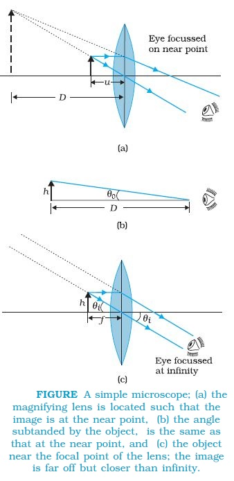
A simple magnifier or microscope is a converging lens of small focal length (Fig.). In order to use such a lens as a microscope, the lens is held near the object, one focal length away or less, and the eye is positioned close to the lens on the other side. The idea is to get an erect, magnified and virtual image of the object at a distance so that it can be viewed comfortably, i.e., at 25 cm or more. If the object is at a distance f, the image is at infinity. However, if the object is at a distance slightly less than the focal length of the lens, the image is virtual and closer than infinity. Although the closest comfortable distance for viewing the image is when it is at the near point (distance D ≅ 25 cm), it causes some strain on the eye. Therefore, the image formed at infinity is often considered most suitable for viewing by the relaxed eye. We show both cases, the first in Fig. (a), and the second in Fig. (b) and (c).
The linear magnification m, for the image formed at the near point D, by a simple microscope can be obtained by using the relation
`m=v/u=v(1/v -1/f)=(1-v/f)`
Now according to our sign convention, v is negative, and is equal in magnitude to D. Thus, the magnification is
`m= (1+D/f).......(1)`
Since D is about 25 cm, to have a magnification of six, one needs a convex lens of focal length, f = 5 cm.
Note that m = h′/h where h is the size of the object and h′ the size of the image. This is also the ratio of the angle subtended by the image to that subtended by the object, if placed at D for comfortable viewing. (Note that this is not the angle actually subtended by the object at the eye, which is h/u.) What a single-lens simple magnifier achieves is that it allows the object to be brought closer to the eye than D.
`text(Angular Magnification :)`
We will now find the magnification when the image is at infinity. In this case we will have to obtained the angular magnification. Suppose the object has a height h. The maximum angle it can subtend, and be clearly visible (without a lens), is when it is at the near point, i.e., a distance D. The angle subtended is then given by
`tantheta_o = h/Dapproxtheta_(o)........(2)`
We now find the angle subtended at the eye by the image when the object is at u. From the relations
`(h^')/h=m=v/u`
we have the angle subtended by the image
`tantheta_i =(h^')/(-v)=h/(-v)*v/u = h/(-u) approx theta` The angle subtended by the object, when it is at u = �f.
`theta_i = h/f............(3)`
as is clear from Fig. (c). The angular magnification is, therefore
`m= (theta_i)/(theta_o) = D/f.......(4)`
This is one less than the magnification when the image is at the near point, Eq. (1), but the viewing is more comfortable and the difference in magnification is usually small.