Amplitude Modulation
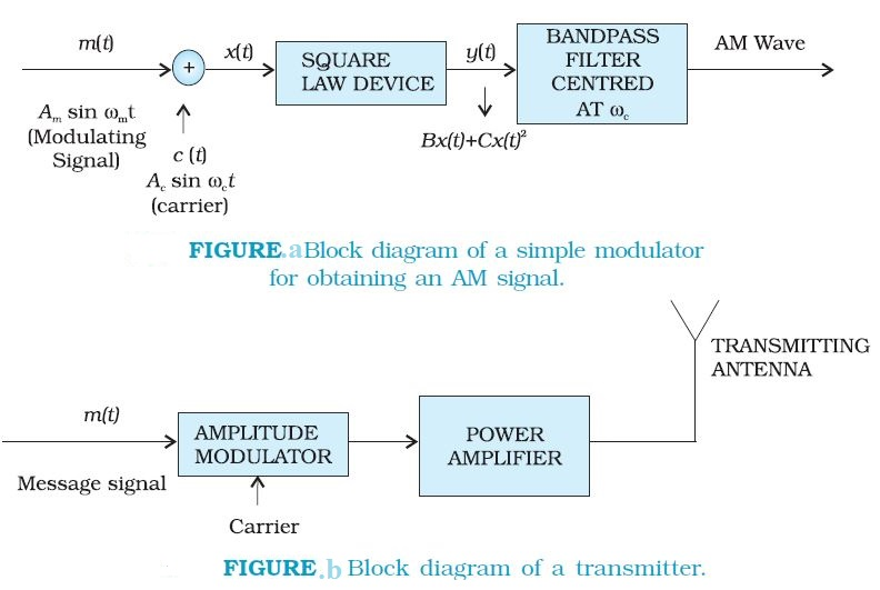
In amplitude modulation the amplitude of the carrier is varied in accordance with the information signal. Here we explain amplitude modulation process using a sinusoidal signal as the modulating signal.
Let carrier wave `=>` `c(t) = A_c sinomega_ct`
modulating signal `=>` `m(t) = A_m sinomega_mt`
where angular frequency `omega_m = 2pif_m`
The modulated signal `c_m (t)` can be written as
`c_m (t) = (A_c + A_m sinomega_mt) sinomega_ct`
`A_c(1+(A_m)/(A_c)sinomega_mt)sinomega_ct--(1)`
Note that the modulated signal now contains the message signal. This can also be seen from Fig. (c). From Eq. (1), we can write,
`c_m( t) =A_c sinomega_ct +muA_csinomega_mtsinomega_ct-..(2)`
Here modulation index(`mu`) = `(A_m)/(A_c)`
`mu` is kept `le1` to avoid distortion.
we can write `c_m (t)` of Eq. (2) as
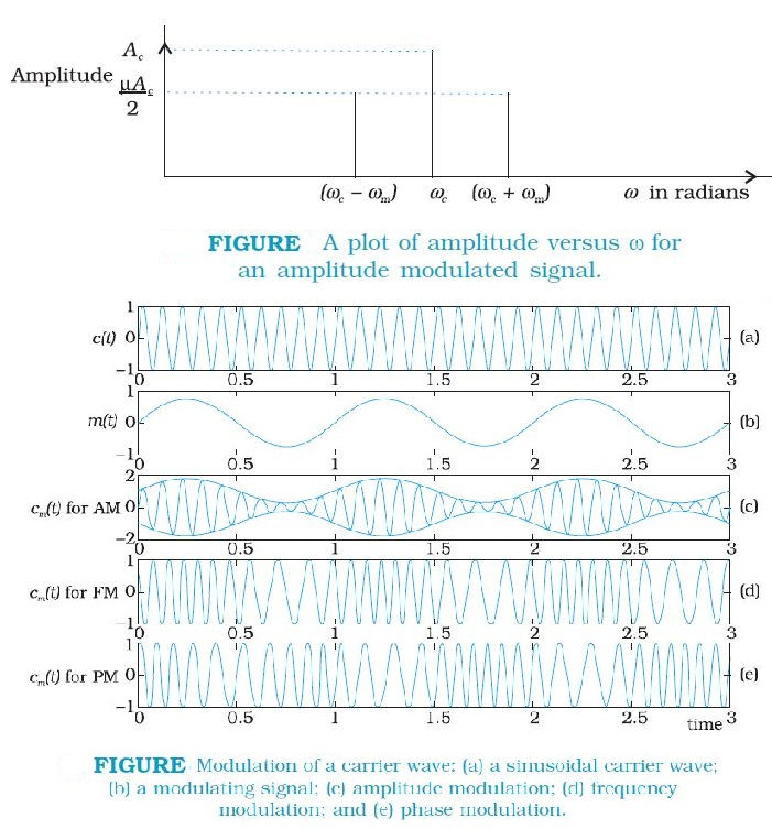
`c_m(t)=A_csinomega_ct+(muA_c)/2 cos(omega_c-omega_m)t-(muA_c)/2 cos(omega_c+omega_m)t-..(3)`
`omega_c-omega_m=>` Lower side frequency
`omega_c+omega_m=>` Upper side frequency
The modulated signal now consists of the carrier wave of frequency `omega_c` plus two sinusoidal waves each with a frequency slightly different from, known as side bands.
As long as the broadcast frequencies (carrier waves) are sufficiently spaced out so that sidebands do not overlap, different stations can operate without interfering with each other.
Let carrier wave `=>` `c(t) = A_c sinomega_ct`
modulating signal `=>` `m(t) = A_m sinomega_mt`
where angular frequency `omega_m = 2pif_m`
The modulated signal `c_m (t)` can be written as
`c_m (t) = (A_c + A_m sinomega_mt) sinomega_ct`
`A_c(1+(A_m)/(A_c)sinomega_mt)sinomega_ct--(1)`
Note that the modulated signal now contains the message signal. This can also be seen from Fig. (c). From Eq. (1), we can write,
`c_m( t) =A_c sinomega_ct +muA_csinomega_mtsinomega_ct-..(2)`
Here modulation index(`mu`) = `(A_m)/(A_c)`
`mu` is kept `le1` to avoid distortion.
we can write `c_m (t)` of Eq. (2) as
`c_m(t)=A_csinomega_ct+(muA_c)/2 cos(omega_c-omega_m)t-(muA_c)/2 cos(omega_c+omega_m)t-..(3)`
`omega_c-omega_m=>` Lower side frequency
`omega_c+omega_m=>` Upper side frequency
The modulated signal now consists of the carrier wave of frequency `omega_c` plus two sinusoidal waves each with a frequency slightly different from, known as side bands.
As long as the broadcast frequencies (carrier waves) are sufficiently spaced out so that sidebands do not overlap, different stations can operate without interfering with each other.